From Backpack Strains to Space Training: Redesigning Astronaut Exercise
PROJECT OVERVIEW
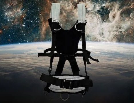
Engineering for Microgravity: The Exercise Harness for Spaceflight
Redesigned astronaut harness systems using sensor-driven, wireless feedback for comfort and load monitoring in microgravity
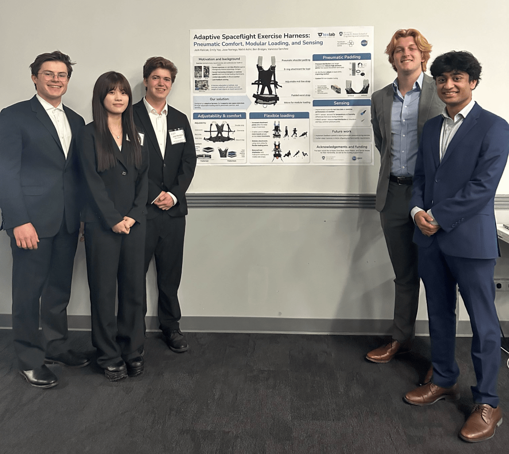
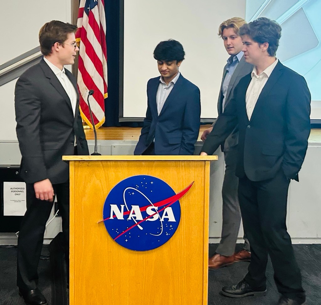
This project tackles the challenge of exercise in zero-g, where traditional harness systems strain and limit effectiveness. Leading the electrical team, I integrated pressure, temperature, and humidity sensors with an ESP32 to monitor load and comfort parameters wirelessly. Through prototyping, circuit calibration, and NASA feedback, I delivered a functional, human-centric prototype in just four weeks.Our team also won the “Best Challenge Response” for our design out of all the participating teams.

What my middle school backpack and NASA’s exercise tech have in common!
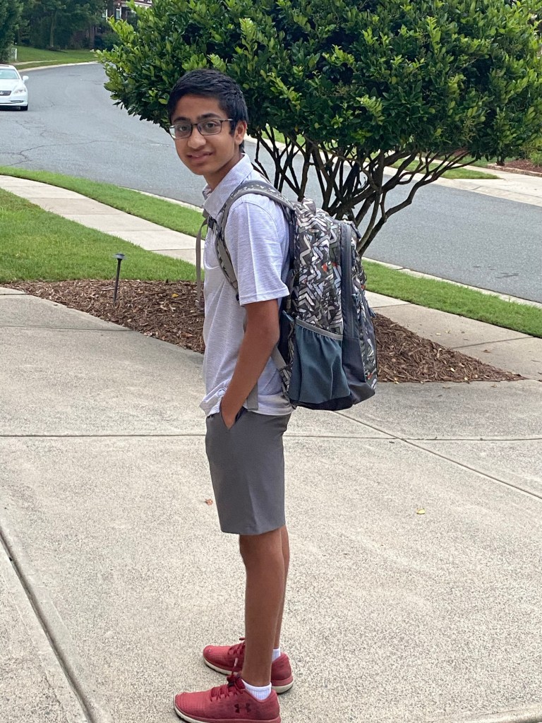
In middle school, I glorified the heavy weight of my backpack. Not only did I feel intelligent because of the load of my textbooks (which, realistically, no one needed to carry as all that information was online even then), but I also believed I was getting important strength training. In truth, the only thing my backpack accomplished was destroying my posture, a problem I’m still recovering from today. Surprisingly, current space exercise technology is built on this same primitive idea.


Exercise Harness Challenge
In zero gravity, the only thing anchoring you down is a set of shoulder straps hooked to the ground, which places an unnatural and uncomfortable load on astronauts. This design leads to less effective and inefficient workouts. NASA challenged us to create a new wearable harness technology that would better replicate physical activity on Earth.
I took the lead on the electrical side of the project, focusing on sensing, feedback systems for data collection, and adaptive control to accommodate a wider range of body shapes
Brainstorming and Sensor Integration
During the brainstorming phase, my main goal was to consider different sensing tools that we could utilize and that could be integrated with the mechanical design. We first drafted a list of potential aspects our harness would aim to address.
In terms of sensing, we knew that pressure was the fundamental component needed to gauge the load on the user. However, with the understanding that our goal was to make a more creative rather than standard design, we wanted more sensors to provide more data for the user to create a better response from the harness.
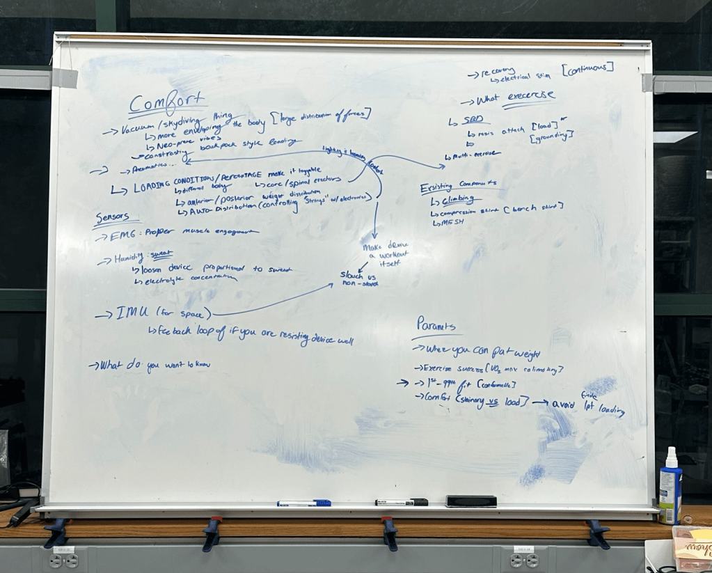
Innovative Sensors for Comfort & Performance
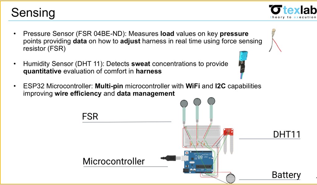
One sensor which allowed better understanding of muscular load was a buckle transducer. Furthermore, a key objective of the design challenge was comfort; however, it was hard to quantify this. Therefore, I attempted to break into the essence of what creates discomfort in the user. I was able to identify that at the highest level, the pressure itself induced heat which could lead to sweat production on the body. We already had a pressure sensor; however, the temperature sensor could identify heat abnormalities due to this pressure, and the humidity sensor could look at the most basic level of determining comfort by identifying regions where sweat was abnormal. Finally when thinking of a microcontroller to use we utilized an ESP32 as it would deal with efficiency with wires in the harness itself to create a less clunky design due to its I2C capabilities as well as having the ability to connect through Bluetooth and Wi-Fi making it easy to connect to and communicate with the device wirelessly. We would power the ESP32 with a 3.7 volt battery.
Consultation
We next had the opportunity to have a conversation with NASA scientists who were also going to be part of the judging for the design challenge. We took the chance to see if our ideas were viable to pursue for the challenge. The judges confirmed that our design seemed viable and doable, as well as emphasized the importance of being creative and that the point of the competition was to bring ideas to NASA that they could refine and implement with their resources and technology. This excited us as it meant we could stand out as a team that had more of a rough but unique response.
Sensor Selection and Initial Testing
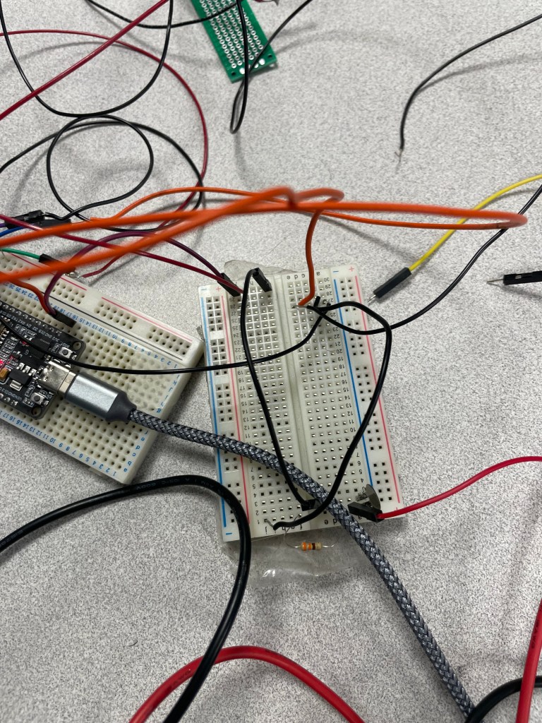
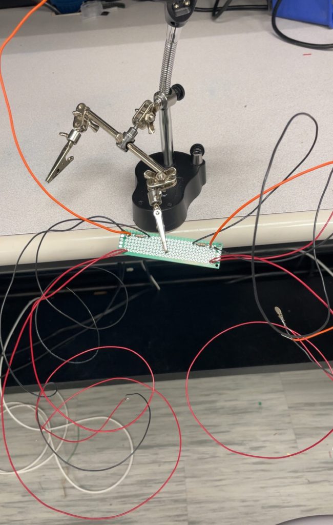
In order to design the sensors, I first had to test if they worked in our harness and were reliable methods to judge the load on the harness. To do this, I did everything on the breadboard first before soldering a final design on perf boards.
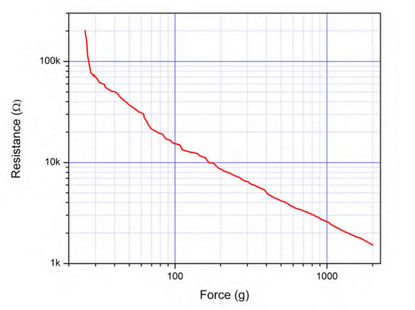
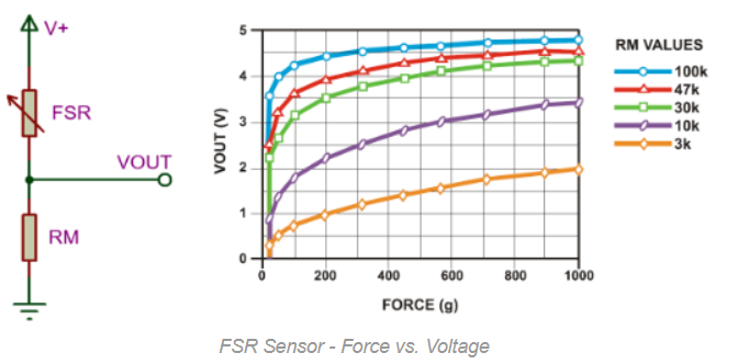
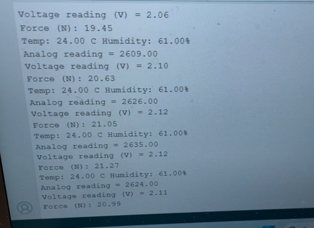
The first technical circuit I had to design was the force sensor. We used an FSR 04BE-ND to measure the force and made a simple circuit using a voltage divider setup. I quickly realized the sensitivity of the values printed by the sensor depended on the resistance we used and found a graph which related the force needed to induce the amount of voltage. The force additionally was given as an output from 0-4095. By using another graph I found online I was able to find the corresponding force in Newtons based on that sensor output value by creating a curve fit equation. I read the values using an analog read pin as well as outputted an analog value (no ADC or DAC needed).
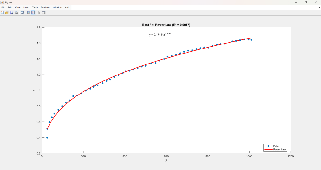

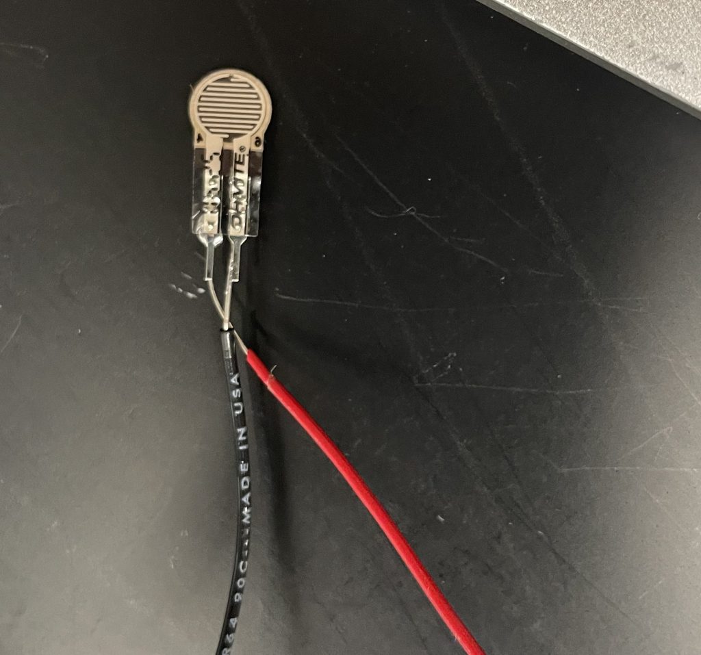
However, the FSR often had flaws in their value readings and differed across different FSRs. I therefore had to recalibrate based on the FSR we used by finding experimental values using a scale and the sensor. I decided to use smaller FSRs in the shoulder in order to have a future ability of packing more sensors there while also getting more precise values at specific locations. In the back due to its more uniform force distribution from the harness I used a larger FSR. Surprisingly the calibration took a while as the force values were not linearly related, so I had to curve fit the values to properly print the force. We tested the FSR on a prototype harness strap and they both worked well showing general regions of high pressure.
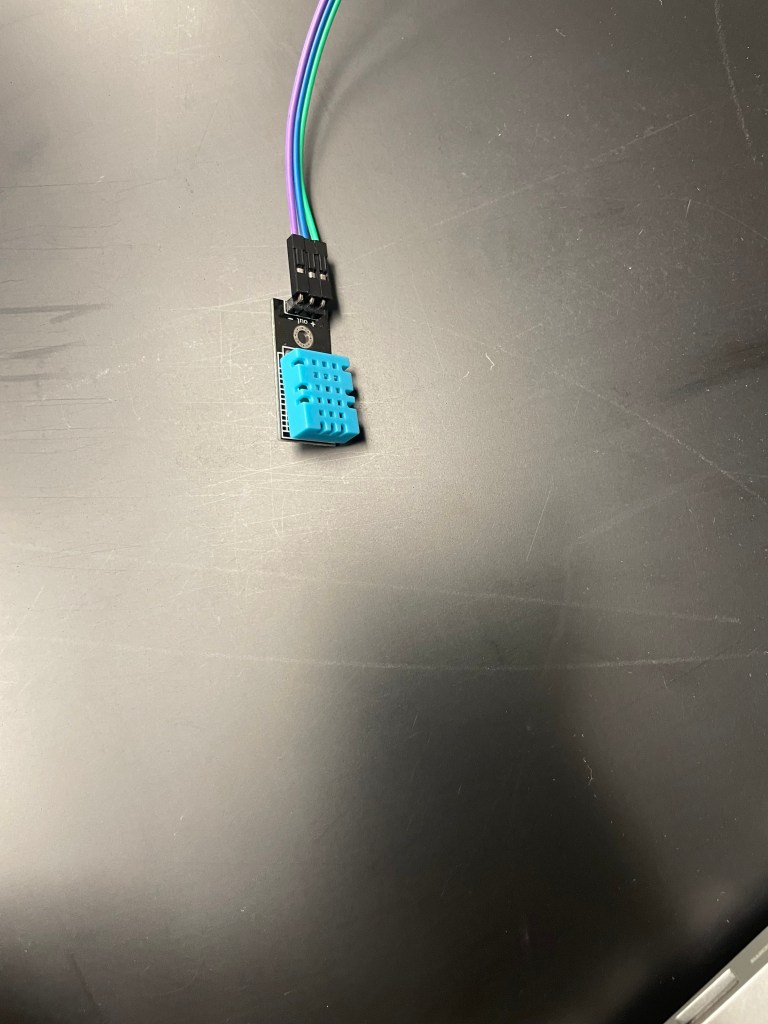
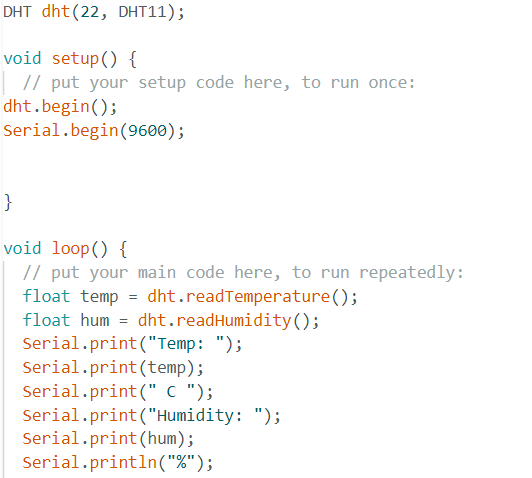
Looking online for humidity and temperature sensors, I found a sensor which included both humidity and temperature sensing: the DHT11. I used the built-in functions to read the temperature and humidity value from the sensor. The sensor was powered by the ESP32 via its power supply and was read directly from the sensor. When we tested it to measure sweat it worked surprisingly well giving a stable and usable sensitivity as well as gave legitimate values based on sweat levels. The temperature sensor also worked as well. In further implementations of the harness, tests would be performed on large sample sizes to gain an understanding of relative humidity levels across different body parts at stable conditions as well as under exercise in order to see what sweat was caused specifically due to the harness being too uncomfortable. If a sweat sensor to measure flow rate or levels is developed this could also be implemented to give an even better understanding however currently no reliable flow rate sensors exist.
Circuit Implementation and Troubleshooting
I was easily able to look up how to perform I2C for this basic circuit however hope to gain more of an understanding of it in the future. Additionally I was able to set up Wi-Fi connection between two ESP32 controllers in order to allow for wireless communication.
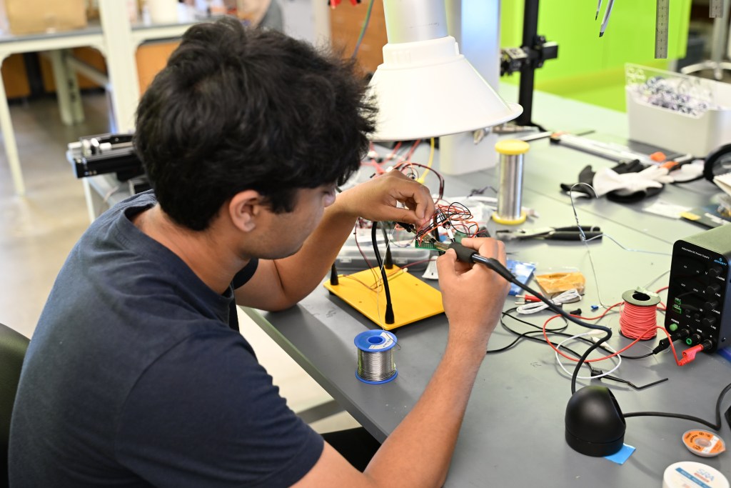
Finally, I soldered my components together. This took a while to do as the soldering on the perf boards was very tricky. I created rail lines for necessary parts such as power and used multiple boards and wires in order to create flexibility and length on the distance between components which could be used to account for varying body sizes. Additionally, I faced an extremely frustrating issue where my components were all of a sudden not reading proper values. I knew my sensors were correct but because I was in the middle of soldering things by replacing their breadboard components it was hard to gauge where a potential error could be. I also had no access to a multimeter at the time as it was late at night and was locked out of the lab but had a MOSFET and LED available so I used the turn on voltage of the MOSFET to test if it would turn on an LED acting as a short or open circuit tester. Although it was a meticulous process it ended up working and I was able to diagnose a hidden open circuit which was faulty in a breadboard rail itself fixing my issue and giving me proper readings.


Final Integration and Results
I finished soldering components and used a heat gun to heat wrap soldered wires together due to the ease in them being able to be broken. This was again a long and slow process due to the nature of the material thicknesses and widths I was soldering.
In the end, I was able to integrate my circuit together into the harness itself with working code giving us a working design in just four weeks.
Reflections: From Textiles to Tech
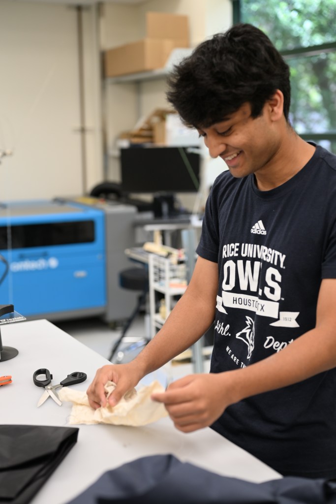
The TexLab at Rice felt like the perfect sequel to my previous work with real-world wearable technology. It also hit close to home as the textile industry had been a major part of my childhood growing up in Gastonia, North Carolina, one of the quintessential cities of America’s textile industry.
The project put me in the unique position of being the only electrical engineer on a team of mechanical engineers. Taking the lead on the electrical hardware and software integration while coordinating with the rest of the team was a fascinating introduction to engineering collaboration and how diverse expertise converges to create an impactful product.
Our sensing system’s unconventional use of a humidity sensor faced pushback during the symposium, but defending it turned into an engaging challenge. By the end of the presentations, I’d even changed a few minds. The experience taught me lessons I’ll carry forward throughout my career.